Access Control Management
Click “Access Control Equipment Management” in the “Access Control Information” drop-down menu of the main interface, as shown in the following figure:

Click “Access Control Management” to enter, as shown in the following figure:
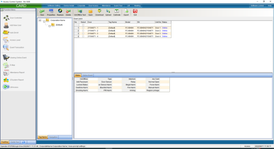
You can also add access control equipment in this interface. Click “Install”in the upper left corner to pop up the interface and install according to the prompts.
Installation and setting of access controller
The automatic search device can automatically search all online access controllers, which is convenient for the device to join the system software. Click “Auto Search Access Control Equipment” in the “Install Equipment” drop-down menu of the main interface, as shown in the following figure:

Click “Auto Search Access Control Equipment” to enter as shown in the following figure:
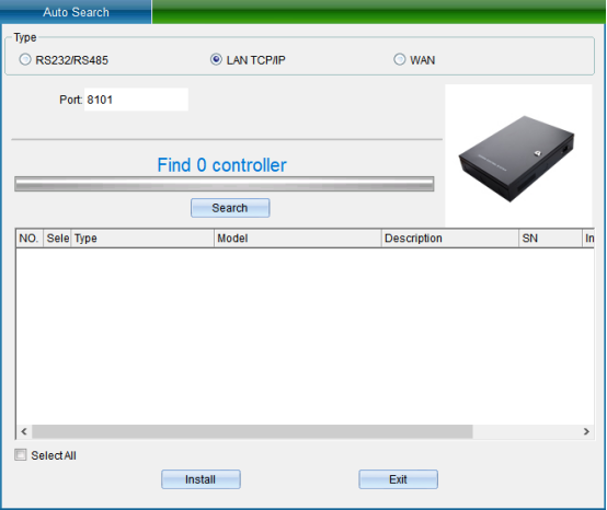
TCP/IP LAN mode: firstly, enter the network port, which is 8101 by default, and then click “Start Search”. (Note: the equipment must communicate with the computer through the switch), as shown in the following figure:
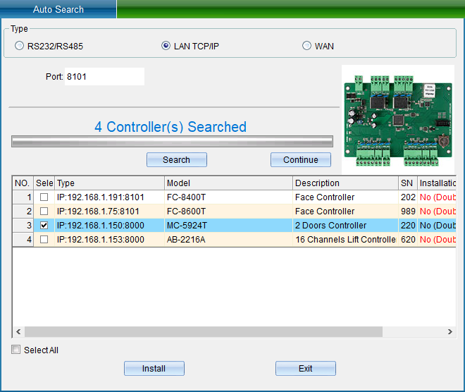
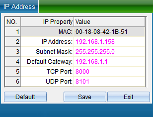
If your device is in TCP/IP communication mode, and you need to modify the device IP address (when installing the device, the user needs to check (device communication password) if the device has modified the communication password, then you need to enter the correct password to allow the modification of the IP address, so as to prevent other people from modifying the device IP through installing software, resulting in the communication failure of the original user). Then you can double-click the TCP/IP controller found to pop up the TCP connection parameter interface, as shown in the following figure:
(Note: the system can search the access controller in a different network segment from the computer, but you need to modify the IP address to the same network segment address as the computer before normal communication. If the router you use supports the multi network segment mapping function, the system software can directly communicate with the access controller of other network segments.)
Double click the IP address, subnet mask and gateway address to change them into parameters matching the computer IP or LAN network segment, click “Save” to return to the installation interface, and then click “Install device” to pop up, as shown in the following figure:
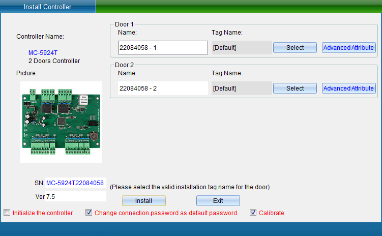
In the interface of “Install Equipment”, you can modify the name, installation position, unlocking holding time, WG byte and other settings of the access controller. If you want to modify the installation location, you can click “Select” to change it, and finally click “Save”. After saving, you can click “Access Control Equipment Management” in the “Access Control Information” drop-down menu to enter, as shown in the following figure:
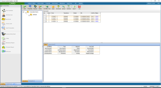
Click the “Attribute” button to pop up the interface as shown in the following figure, and select “Communication Parameters”:
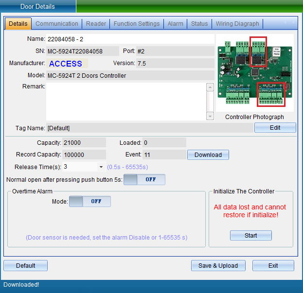
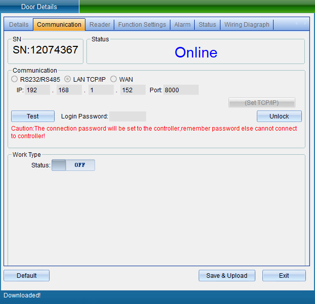
Select “Unlock Parameters” to pop up the verification password window in the figure below, enter the default password: 0000, and enter the setting of TCP connection parameters, as shown in the figure below:
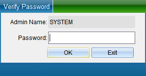

In the TCP connection parameters interface, double-click to modify the IP address. After modification, click “Save”. A window will pop up indicating success. Click “OK” to modify the IP address successfully. After modification, you need to test whether it can be connected, as shown in the following figure:
Click “Test Connection” to test. After the connection is successful, a window will pop up, and then click “OK”. If you find that the equipment time is wrong, you can click “Calibration Time” to calibrate. Click “Save” and a window will pop up indicating success. Click “OK” to finish setting parameters, and then click “Exit”.
In the communication parameter interface, you can also modify the access controller WG output type, WG byte order, access category, card number byte and other equipment parameters.
Add people and authorize
Click “Personnel File” in the drop-down menu of “Access Control Information”, as shown in the following figure:
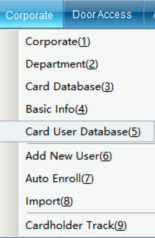
Click the “Personnel File” to enter, as shown in the following figure:
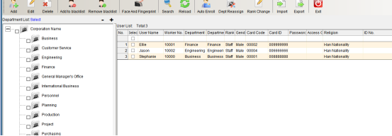
Click “Add” to enter as shown in the following figure:
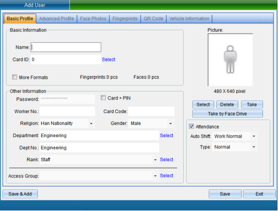
After filling in the personal information, click Save.
Click “Set Door Opening Authorization” in the “Access Control Information” drop-down menu (this function is not available in the default interface. If you want to enable more required functions, you can click “Open Function” in the “Help” drop-down menu in the upper right corner of the main interface to open more functions), as shown in the following figure:
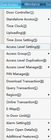
Click “Set Door Opening Authorization” to enter, as shown in the following figure:
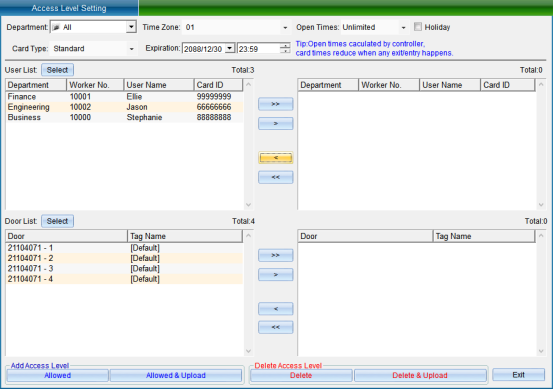
Select the person who needs to set the access control permission, select the opening period and times, the validity period, and select the equipment door. After selecting, click “allow the selected person to pass through the selected door and upload”.
[> ]: select all “Users” or all “Optional Doors”.
[>]: select a single “User” or a single “Optional Door”.
[<]: remove a single “Selected User” or a single “Selected Door”.
[< ]: remove all “Selected Users” or all “Selected Doors”.
“Prohibit the Selected Personnel from Passing through the Selected Door”: to delete the access permission of the specified user to the selected door, you must upload the settings in the synchronous data before the deletion of the permission can take effect.
[Prohibit selected personnel from passing through the selected door and uploading]: delete the user's access permission to the selected door and upload it to the controller at the same time, and there is no need to upload to the synchronization data.
[Allow selected personnel to pass through the selected door]: add the access permission of the specified user to the selected door. The added permission can only take effect after the settings are uploaded in the synchronous data.
[Allow selected personnel to pass through the selected door and upload]: add the access permission of the specified user to the selected door and upload it to the controller at the same time, without uploading to the synchronization data.
After selecting users and doors, all records can be arranged by door or by user, and you can clearly see which people are allowed to enter and exit a door and which doors a person can enter and exit.
After all permissions are set, upload the settings of the specified door to the controller.
Device Attribute Settings
Modify Device Information
Equipment information includes equipment name, SN, control port, manufacturer, version number, equipment model, installation location, equipment card capacity, unlocking holding time, door opening timeout prompt, initialization equipment, etc.
In the “Equipment Properties” interface, click “Setting Information”, as shown in the following figure:
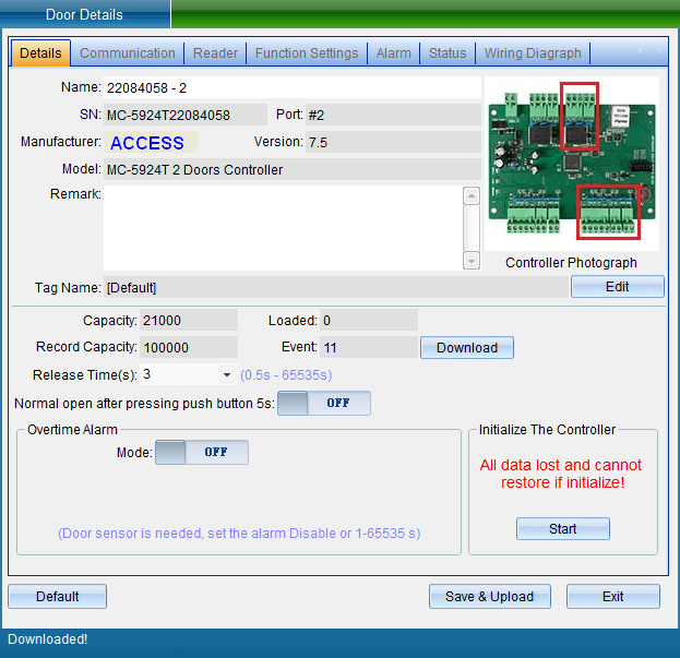
Equipment name: can be modified as required.
Unlocking holding time: it can be adjusted according to needs. (default: 3 seconds)
Modify device IP and port
Select the equipment to be modified, and then click "Properties", as shown in the following figure:
1. Modify IP address
Click the “Attribute” button to pop up the interface as shown in the following figure, and select “Communication and Port”:

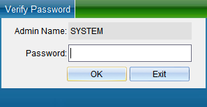
Select “Unlock Parameters” to pop up the verification password window in the figure below, enter the default password: 0000, and enter the setting of TCP connection parameters, as shown in the figure below:
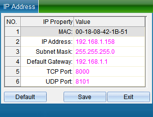
In the TCP connection parameters interface, double-click to modify the IP address. After modification, click “Save”. A window will pop up indicating success. Click OK to modify the IP address successfully. After modification, you need to test whether it can be connected, as shown in the following figure:
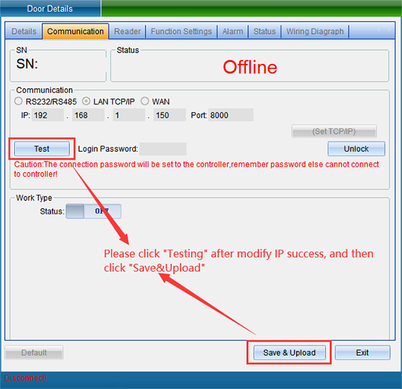
Click “Test Connection” to test. After the connection is successful, a window will pop up, and then click “OK”. If you find that the equipment time is wrong, you can click “Calibration Time” to calibrate. Click “Save” again, and a window will pop up indicating success. Click “OK” to finish setting parameters, and then click “Exit”.
2. Modify the device communication password
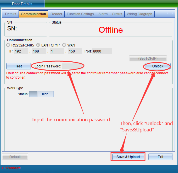
In the “Equipment Properties” interface, select “Communication and Port”, enter the communication password, click “Lock Parameters”, and then click Save. As shown in the following figure:
Communication password: you can confirm the password during communication to achieve a more secure level. (remember to keep it.)
Replace Equipment
When there is a problem with the equipment, copy the permission parameters of the original equipment to the new equipment by replacing the equipment of the same model. Click “Replace” in the “Access Control Equipment Management” interface to open the interface, as shown in the following figure:
Enter the SN code of the new device and click “New Communication Information” to open the communication information window, as shown in the following figure:

Change the IP address parameters of the new device, click “Save”, and select whether to use the parameters of the original device as needed. After selection, click “confirm replacement and import data”, and click “Exit”.
Calibration Equipment Time
To calibrate the equipment time, click “Calibration Time” in the menu bar in the “access control equipment management” interface or click “Calibration Equipment Time” in the drop-down menu of “Access Control Information” in the main interface of the software, as shown in the following figure:
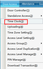
Click “Calibrate Equipment Time” to enter the interface as shown in the following figure:
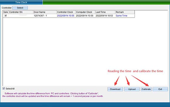
Use the clock of the computer system to calibrate the clock of the controller, so as to achieve the time synchronization between the access control intelligent management system and the controller. Please make sure whether the computer time is accurate first. Select the door you want to calibrate and click “Calibration Time”.
Upload Access Control Data
To upload data, click “Upload Data” in the “Equipment Management” interface or click “Upload Data” in the drop-down menu of “Access Control Information” in the main interface of the software, as shown in the following figure:
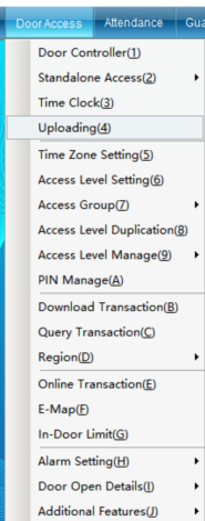
Uploading data is to upload the uploaded personnel, opening period, opening password and equipment parameters to the equipment at one time after setting them respectively. Click “Upload Data” to enter as shown in the following figure:
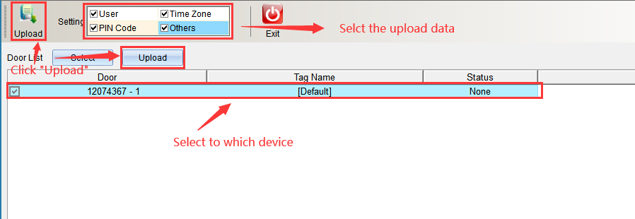
Select the content to be uploaded in the upload content, either single or all, and click “Start Uploading” after selecting the equipment. Enter as shown in the following figure:
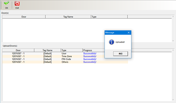
After uploading, a prompt window will pop up. Click “OK” in the window to finish uploading data. Click “Finish” and “Exit” to return to the main interface.
Copy permissions
Click “Copy Permission” in the “Access Control Information” drop-down menu, as shown in the following figure:
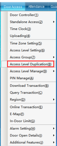
If user A has the same permissions as other users, you can copy the permissions of user a to other users through “Copy Permissions”. Click “Copy Permission” to enter the interface shown in the following figure:
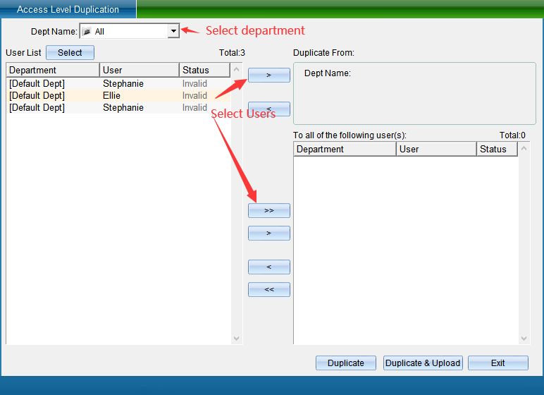
Select the personnel of a single department or all departments in the Department name, select the personnel who have the permission to open the door, and then select a single or all personnel without permission to the “copy to the following personnel” box, and then click “Copy Permission” (here, only copy the permission and not update it to the equipment) or “copy permission and download” (here, both copy the permission and update the permission to the equipment), and then click “Finish”.
Opening time management
If you want to set users' personalized permissions. For example, who can enter which doors from what time to what time, and who can enter which doors on the day of the week. Please set the “Door Opening Period” function, and multi period control can be achieved through the period. Such as special working conditions on Saturday and Sunday.
Click “Door Opening Period Management” in the drop-down menu of the software menu “Access Control Information” (this function is not available in the default interface. If you want to enable more required functions, you can click “Enable Function” in the drop-down menu of “Help” in the upper right corner of the main interface to enable more functions), as shown in the following figure:
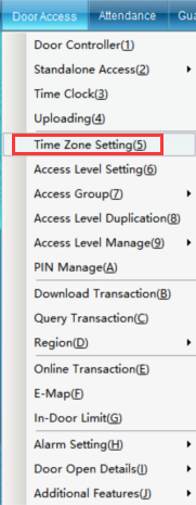
Click “Door Opening Period Management” to enter the interface shown in the following figure:
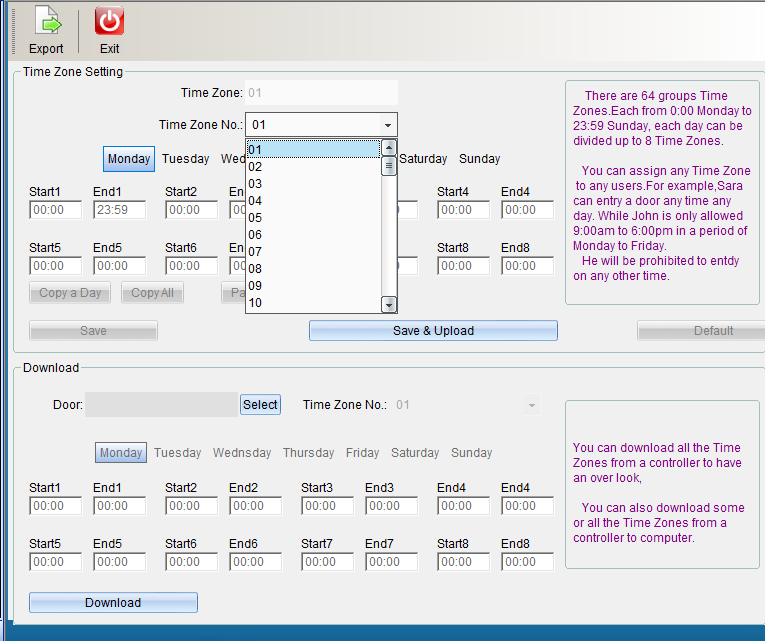
Default data: 01 group of time periods, from Monday to Sunday, are valid for 24 hours, while 02-64 group of time periods are invalid by default. To add a new opening time period, you can click opening time period 02 to start adding a time period, as shown in the following figure:
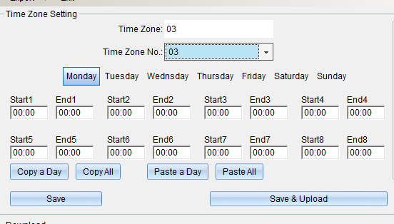
1. The name of the opening period can be changed. The opening period can be set with 8 different period limits from Monday to Sunday.
2. You can copy the set time period to the time of other weeks.
If the time is set in “Monday”, click “Copy Single Day Data”, click “Tuesday”, select “Paste Single Day Data”, and the same is true from Wednesday to Sunday. Set the completion point “Save Period Database” or click “save and upload to all access controllers”, and click “Finish” to exit after uploading the period.
If you need more than one time period, and most of the time is the same, you can copy the whole time period and paste the whole time period. If the time of time period 2 has been set and saved, you can click “copy the whole time period”, click time period 3, click “paste the whole time period” to copy the opening time of time period 2 to time period 3, and then click “save and upload to all access controllers”.
If “door opening period management” is not required, click “restore to system default”.
After setting the time period, if you need to assign a time period to the user, you need to assign the time period to the corresponding user in “Permission” before you can control the user to enter and exit the specified door in the specified time period.
Permission Group Management
Click the software “Access Control Information” drop-down menu “Permission Group Management” as shown in the following figure:
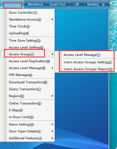
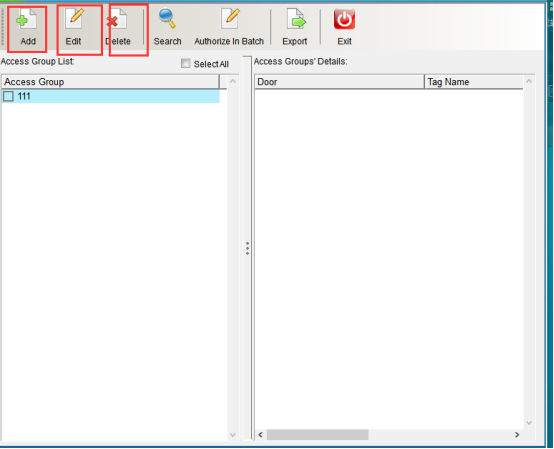
You can add, modify and delete permission groups, as shown in the following figure
Add permission group
Click the software “Access Control Information” drop-down menu “Permission Group Management” to enter the permission group management interface, as shown in the following figure:
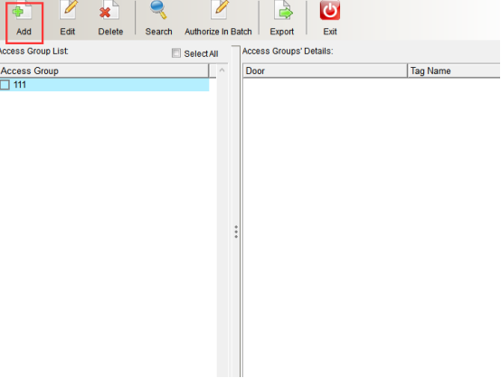
Click “Add” to enter, as shown in the following figure:
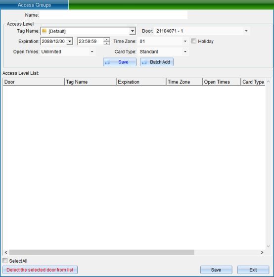
Fill in the name of the permission group on this page, select the door to be authorized, and set the validity period, opening period, opening times, whether to open on holidays and special permissions of the whole group. After filling in, click “Save to List” to appear in the blank list below. If you find an error, you can click “delete the checked door from the list” to delete and add again. Finally, click “Save”, and a pop-up prompt will appear indicating that the saving is complete. Click “OK”. (upload on the page of setting personnel permission group)
Modify Permission Group
Click “Permission Group Management” under “Permission Group Management” in the software “Access Control Information” drop-down menu, and select the permission group to be modified,
Click “Modify” to enter, as shown in the following figure:

Delete Permission Group
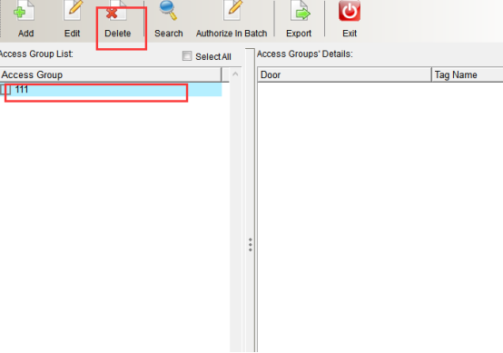
Click the software “Access Control Information” drop-down menu “Permission Group Management”, select the permission group to be modified, and click “Delete”. This operation requires entering the operator login password for confirmation before it can be successfully deleted. As shown in the following figure:
Set personnel permission group
Click “Set Personnel Permission Group” under “Permission Group Management” in the software “Access Control Information” drop-down menu, as shown in the following figure:
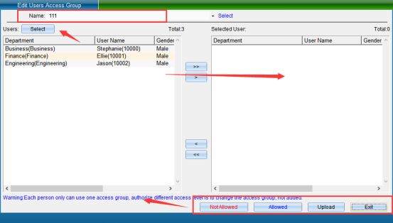
Firstly, select the name of the permission group, then select the personnel to be assigned to the permission group from the personnel list and pull it to the right. If there are too many people, you can click “Filter” to enter, as shown in the following figure:
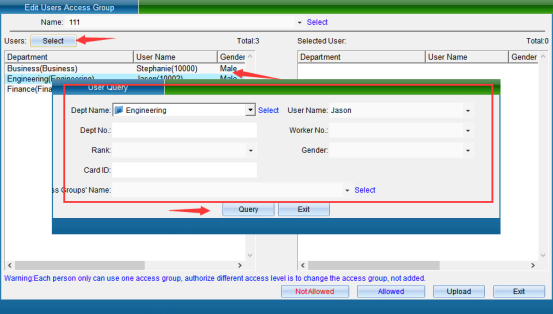
Select a person and pull it to the right. You can click “Permission Group Management” to delete the permission of the person who has joined this permission group. You need to re join the point “Allow Permission Group”. Both operations need to finally click “Upload Permission”.
Uploading data is to upload the stored personnel, opening period, opening password and equipment parameters to the equipment at one time after setting them respectively. After selecting them, click “Start Uploading”. The interface is shown in the following figure:
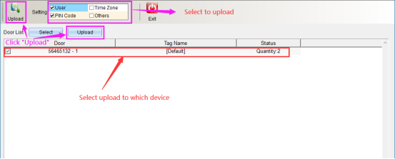
After uploading, a prompt window will pop up. Click “OK” in the window to finish uploading data. Click “Finish” and exit to return to the main interface.
Personnel permission group report
Click “Personnel Permission Group Report” under “Permission Group Management” in the software “Access Control Information” drop-down menu, as shown in the following figure:
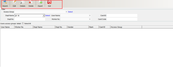
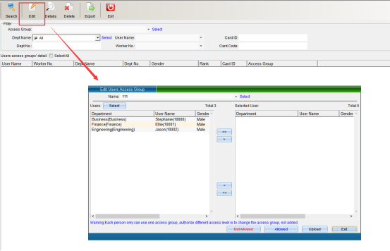
In the filter criteria column, you can accurately find information such as department name, personnel name, card number, department number, personnel number and card word number. Click “Search” to find the information, you can select the person to modify and click “Edit Permission” to modify. As shown in the following figure: please refer to setting personnel permission group for details
Click “View permission details” to view the permission details of the selected person, as shown in the following figure:
After viewing the information of this person, if there is an error, you can click “Delete”. This operation requires the operator to enter the software login password for confirmation. As shown in the following figure:
Check the door opening permission by person / door
Click “Door Opening Permission Management” in the “Access Control Information” drop-down menu, as shown in the following figure:
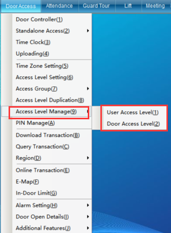
You can query the permission to open the door by person or by door.
Display door opening permission by personnel
Click “Display Door Opening Permission by Person” under “Door Opening Permission Management” in the “Access Control Information” drop-down menu to enter as shown in the following figure:

Select the Department and name of the person, and click “Search” to display the door opening permission of the selected person, as shown in the following figure:
If you do not select any conditions, click “Search” to display the door opening permission of all personnel, or you can enter the personnel name or card number and other information to view. And you can click “Export” to save the data to the computer. You can also click “Print” to view the paper data. As shown in the following figure:
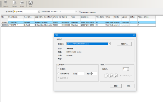
Select the printer, set the number of copies and format, and click OK.

Display door opening permission by door
Click “Display Door Opening Permission by Door” under “Door Opening Permission Management” in the “Access Control Information” drop-down menu, as shown in the following figure:
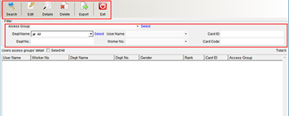
Select the installation position of the equipment, that is, the door; Different doors correspond to different devices, and then click “Search” to display the permissions of the personnel assigned to the selected door, and click “Export” to export the content displayed in this interface and save it to the computer. You can also click “Print” to view the paper data. As shown in the following figure:
Select the printer, set the number of copies and format, and click OK.
Create a door opening password
By installing a keyboard card reader, you can enter the door after entering the super password on the card reader. This function is mainly used by users with special identities or users who do not need to wear cards.
Click “Door Opening Password Management” in the drop-down menu of the software menu “Access Control Information” (this function is not available in the default interface. If you want to enable more required functions, you can click [enable function] in the drop-down menu of [help] in the upper right corner of the main interface to enable more functions) as shown in the following figure:
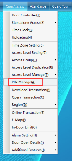
Click “Door Opening Password Management”, as shown in the following figure:
Set the “Door Opening Password”, which can be set for all controllers or one controller. Up to 100 sets of door opening passwords can be set. After entering the 4-8 digit door opening password, click “Select” to pop up the interface as shown in the following figure:
After selecting the location, return to the “Door Opening Password Management” interface, as shown in the following figure:

After setting the password and location successfully, click “Add Password and Upload to the Device”, and a prompt “Password Updated Successfully” window will pop up. Click “OK”, and the added password record information will be displayed in the password table box, showing that the upload is complete. Enter the correct password on the keyboard of the access card reader and press # or ENT to confirm, and then directly open the corresponding door to enter. And there are records and displays in the data monitoring.
Collect Access Records
The system is equipped with memory storage function, and each controller can store records offline (even if the computer is not turned on, it will be stored automatically. The records will never be lost after power failure). You can select the appropriate time to extract the data into the computer. After the extraction is successful, the system will automatically delete the records in the controller.
Click the “Access Control Information” drop-down menu “Collect Access Records” of the software, as shown in the following figure:
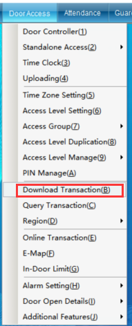
Click “Acquisition Access Record” to enter the interface shown in the following figure:
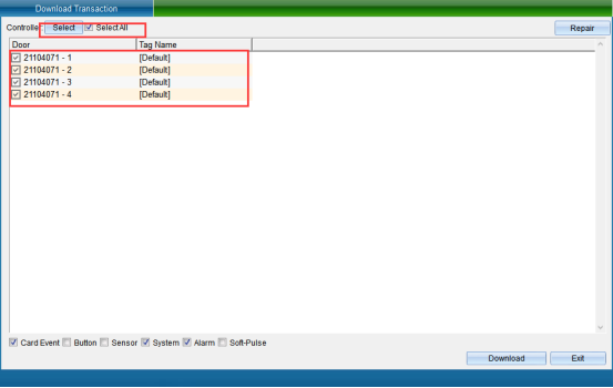
After selecting the record of which device to collect, click “Collect Selected Device Record” to pop up the window as shown in the following figure:
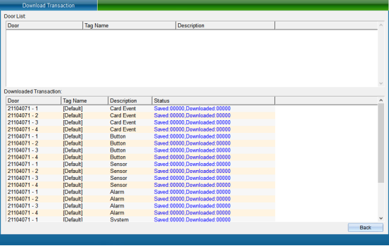
After the collection is completed, click “Finish”.
If you have collected card reading records before, you can retrieve all records through “Repair Records”.
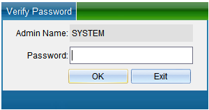
Click “Repair Record” in the “Acquisition Record” interface of the “Access Control Information” drop-down menu of the software, and the following verification window will pop up. Enter the verification password: 0000, and then click “OK”, as shown in the following figure:
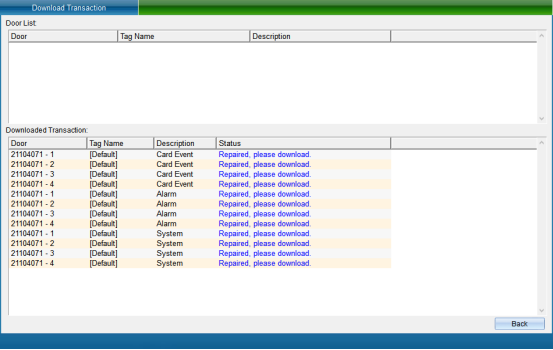
Click “Finish”to return to the interface of collecting access control records, select the door to extract the card reading records and the data to be collected, and then click “Collect Records of the Selected Equipment”, wait a moment to complete the collection. At this time, all the records in the controller are collected into the computer, as shown in the following figure:
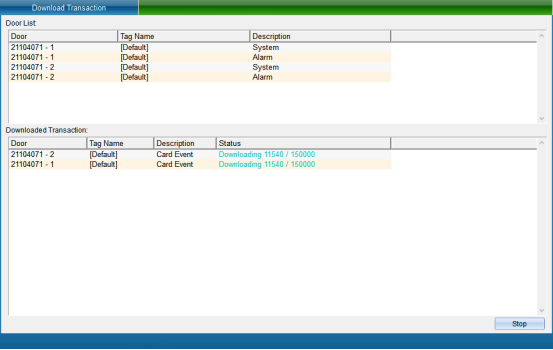
Wait for the collection completion point “Complete”. The query can be carried out only after the records are collected.
View Access Records
Please collect the records before querying.
Click “View Access Record” in the drop-down menu of “Access Control Information” in the software menu bar, as shown in the following figure:
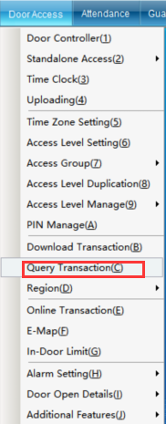
Click “View Access Record” to enter as shown in the following figure:
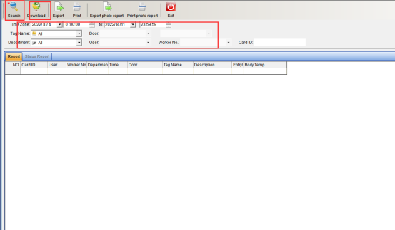
Firstly, collect the records, click “Collection Records”, you can refer to (1.9 collection access records). After collecting the records, you can query as needed and enter the query criteria. The query criteria can be based on “Time Range”, “Name”, “Card Number”, “Department”, “Location” to query the relevant records, and then click “Search” to query the access records of relevant personnel, or directly click “Search”, the access conditions of all people will be queried, as shown in the following figure:
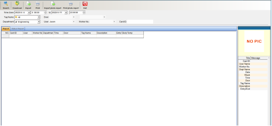
You can also export the queried records. Click “Export” to export personnel access records.
Alarm Function Setting
If you want the door to be forced to open, open the door overtime, access control bandits, unregistered card swiping and other situation, you can quickly get the alarm information in the data monitoring, so as to take action immediately.
Please note: when using the “Access Control Bandit Alarm” function, the hardware equipment must be connected to the door magnetic signal and installed with an expansion module.
Click “Access Control Information” - “Alarm Function Setting”, as shown in the following figure:
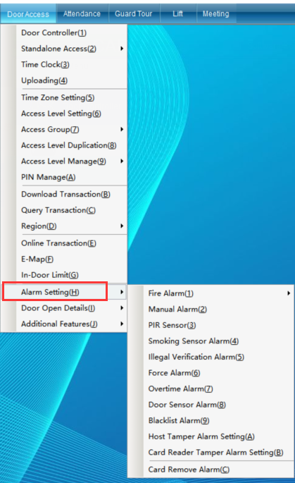
It can set access control and fire protection settings, access control bandit alarm settings, anti-theft host settings, smoke alarm settings, unregistered card alarm, door opening timeout alarm and other event alarms.
Access control and fire protection settings
Click “Access Control Information” - > “Alarm Function Setting” - > “Access Control Fire Protection Setting” - > “Fire Alarm Management” in the software menu bar (the default interface does not have this function. If you want to enable more required functions, you can click “Enable Function” from the “Help” drop-down menu in the upper right corner of the main interface to enable more functions) as shown in the following figure:
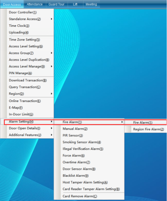
Fire Alarm Management
Click “Access Control Information” - > “Alarm Function Setting” - > “Access Control Fire Protection Setting” - > “Fire Alarm Management” in the software menu bar to enter, as shown in the following figure:
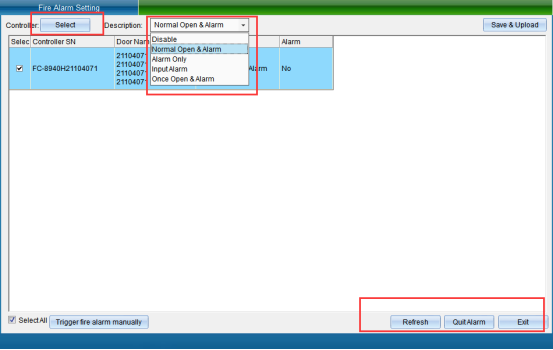
Firstly, select the equipment that needs to set access control and fire fighting, and then select the fire fighting mode (function off, alarm opening, alarm not opening, signal alarm, no signal release, all doors open once when there is a signal), and then click “Set Fire Fighting Mode”, as shown in the following figure:
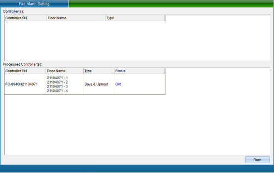
Click “Finish” to set the fire protection mode successfully. You can also directly trigger fire access control, and click “Trigger Fire Access Control”, as shown in the following figure:
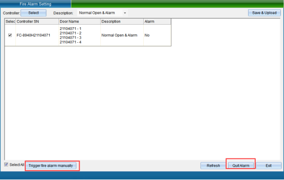
Clicking “Trigger Access Control Fire Alarm” will trigger equipment alarm, so that personnel can quickly know the situation. To turn off the alarm, you need to click “Stop Alarm”.
Regional fire fighting
Click “Access Control Information” - > “Alarm Function Setting” - > “Access Control Fire Protection Setting” - > “Area Fire Protection” in the software menu bar.
Area fire protection: it can realize the linkage alarm function of multiple controllers (it needs to build an area first to linkage). If the user wants to have a correlation between several doors, and wants to make the fire alarm, when the doors of the whole floor alarm and open the door. The area fire protection can be enabled, as shown in the following figure:
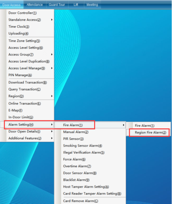
Click “Area Fire Protection” to enter the interface shown in the following figure:
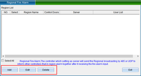
Click “Add” to enter as shown in the following figure:
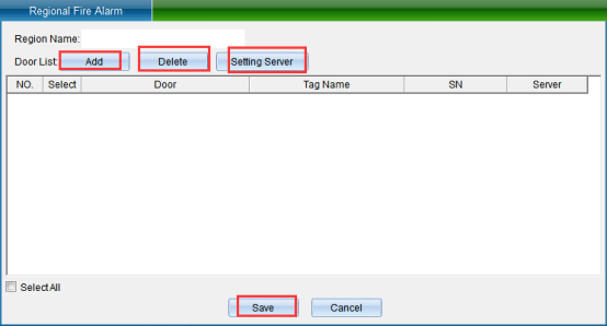
Enter the area name in the “Area Name” input box, and then click “Add Door”, as shown in the following figure:
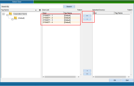
After selecting the door, click “Select” to see the selected door in the interface, as shown in the following figure:

Enter the area name, select the door that needs to be set as the master controller, and then click “set as the master controller” to display the selected door as the master controller. Click “Save” to enter the upload interface, as shown in the following figure:
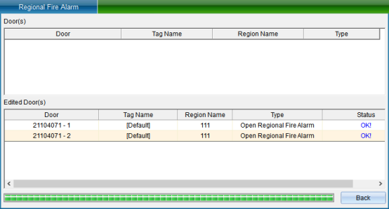
Click “Finish” to see that the set area exists in the area list in the area fire fighting interface, as shown in the following figure:
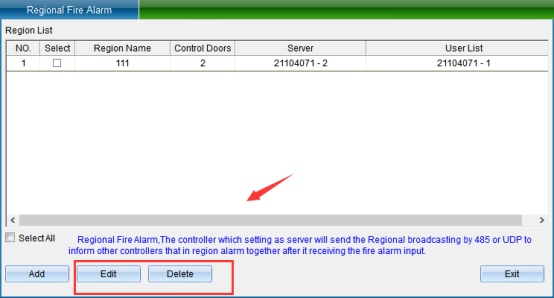
You can also modify and delete the selected area.
After setting one of the doors as “main controller”, the set parameters and data will be saved in the main controller, and finally click “save”. (the entire area data is stored in the “main controller”. If the main control is not online or fails, this function will fail, so the application of this function should protect the “main controller”.)
Note: 1. No more than 10 controllers are recommended for fire protection in each area
2. TCP/IP communication mode must be used for communication.
3. The network communication must be connected normally. If the network connection is not normal, the controller in this area may be paralyzed.
Access control bandit police settings
Access control bandit police setting: the door is opened after it has not been swiped legally, and the bandit police mode can be selected.
Click “Access Control Information” - > “Alarm Function Setting” - > “Access Control Bandit Police Setting”, as shown in the following figure:
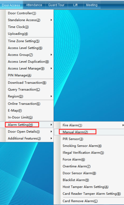
Click “Access Control Bandit Police Settings” to enter the interface shown in the following figure:
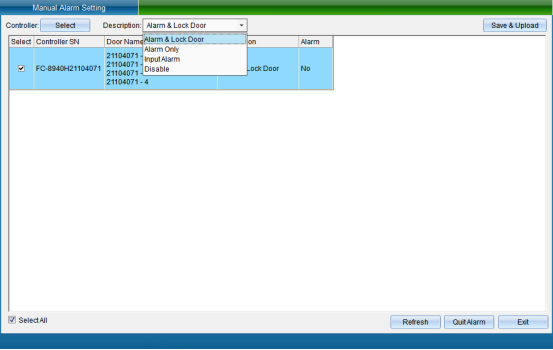
Select the equipment that needs to set the access control bandit alarm function, select the bandit alarm mode (function off, alarm and lock the door, alarm does not lock the door, signal alarm, no signal release), and then click “Set Bandit Alarm Mode” to enter the interface as shown in the following figure:
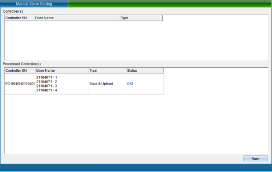
Click “Finish” to set the bandit alarm mode successfully, and then click “Exit” to return to the main interface of the system.
Anti Theft Host Settings
Anti theft host setting: this function is mainly used to set this function for personnel with use or management rights when leaving. The time of entry delay and alarm delay setting is the time of personnel leaving. If entering again, the alarm will be triggered.
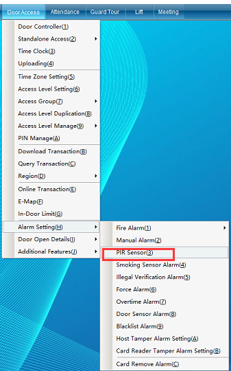
Click “Access Control Information” - > “Alarm Function Setting”- > “Anti Theft Host Setting”(this function is not available in the default interface. If you want to enable more required functions, you can click [enable function] in the [help] drop-down menu in the upper right corner of the main interface to enable more functions), as shown in the following figure:
Click “Anti Theft Host Setting” to enter the interface shown in the following figure:
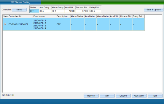
Select the device that needs to set the anti-theft host function, then turn on the function and set the relevant content, click “Save and Upload” to enter the upload interface, as shown in the following figure:
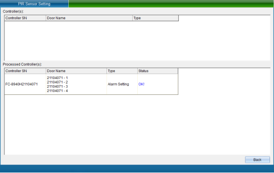
Click “finish” to finish setting the anti-theft alarm mode.
“Anti Theft Host Setting” the above anti-theft alarm output delay is the set “entry delay”. If the alarm signal does not recover within the “entry delay”, after the alarm signal returns to normal, the alarm output will automatically reset, and the anti-theft alarm output will be reset when disarming.
Entry Delay: leave by yourself within the set delay time for deployment / withdrawal
Alarm Delay: after the entry delay is exceeded, when someone enters again, the signal alarm delay will be triggered
Arming Password: enter the arming password directly on the keyboard with password to enter the arming state
Disarm Password: after opening the door, you must enter the setting password within the specified time to disarm
Alarm Duration: the duration of driving alarm
Click to reset the above settings
Smoke Alarm Setting
Click “Access Control Information” - > “Alarm Function Setting” - > “Smoke Alarm Setting” to set the smoke alarm function (this function is not available in the default interface. If you want to enable more required functions, you can click [enable function] in the [help] drop-down menu in the upper right corner of the main interface to enable more functions), as shown in the following figure:
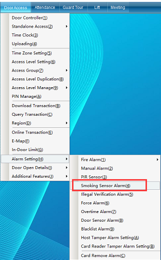
“Smoke Alarm Setting”: corresponding to the smoke gas temperature alarm, you can choose the smoke mode according to your needs. You can choose to click “Trigger Fire Alarm” or “Stop Alarm”.
Click “Smoke Alarm Setting” to enter the interface shown in the following figure:
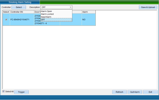
Select the equipment that needs to set the smoke alarm of access control, select the smoke mode, and then click “Set Smoke Alarm Mode” to enter the interface as shown in the following figure:
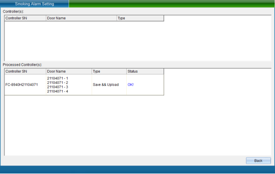
Click “Finish” to set the smoke alarm successfully.
You can also directly trigger the smoke alarm. Click “Trigger Alarm”, as shown in the following figure:
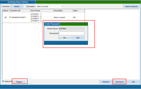
After clicking “Trigger Alarm”, the verification password window will pop up, enter the operator password, and click “Verify”, the alarm will be triggered successfully. To stop the alarm, click “Stop Alarm”.
Unregistered Card Alarm
Click “Access Control Information” - > “Alarm Function Setting”- > “Unregistered Card Alarm” (this function is not available in the default interface. If you want to enable more required functions, you can click “Enable Function” in the drop-down menu of “Help” in the upper right corner of the main interface to enable more functions), as shown in the following figure:
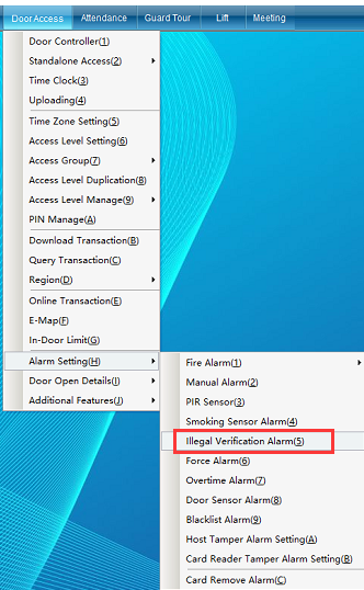
“Unregistered Card Alarm Setting”: the door will alarm after the unregistered card is swiped. If you want to eliminate the alarm, you can click “stop alarm”.
Click “Unregistered Card Alarm” to enter the interface shown in the following figure:

Select the device that needs to set the alarm function of unregistered card, select whether to turn on the alarm mode, and then click “Set Alarm Mode” to enter the interface as shown in the following figure:
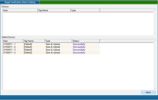
Click “Finish” to set the unregistered card alarm successfully.
Duress alarm settings
Click “Access Control Information” - > “Alarm Function Setting” - > “Duress Alarm Setting” (this function is not available in the default interface. If you want to enable more required functions, you can click [enable function] in the [help] drop-down menu in the upper right corner of the main interface to enable more functions), as shown in the following figure:
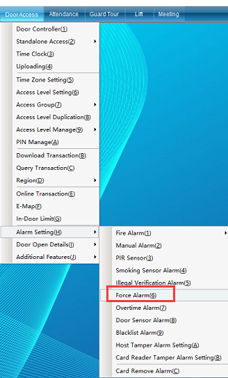
“Coercion Alarm Setting”: people are coerced by gangsters. If they don't open the door, their lives will be threatened. They have to open the door as a last resort. They can use coercion passwords to open the door. Although the door was opened, the data monitoring will show that the door was forced to open and take measures. The life of the cardholder will not be threatened. The coercion password is 119119 (changeable), and this function must be used in conjunction with the password keyboard reader (the coercion alarm modes are: alarm, open the door once and then lock; alarm, do not open the door; alarm, lock the door).
Click “Duress Alarm Setting” to enter the interface shown in the following figure:
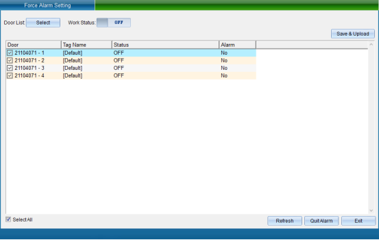
Select the equipment that needs to set the coercion alarm, turn on the working state, select the alarm mode, enter the coercion password, and then click “Save and Upload” to enter the interface as shown in the following figure:
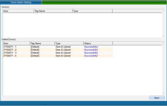
Click “Finish” to finish setting the coercion alarm function.
Door Opening Timeout Alarm
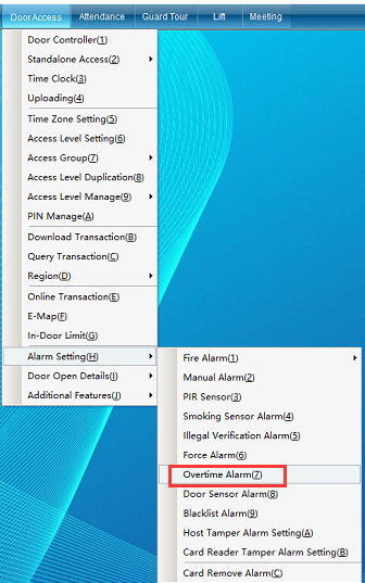
Click “Access Control Information” - > “Alarm Function Setting” - > “Door Opening Timeout Alarm”, as shown in the following figure:
Click “Door Opening Timeout Alarm” to enter the interface shown in the following figure:
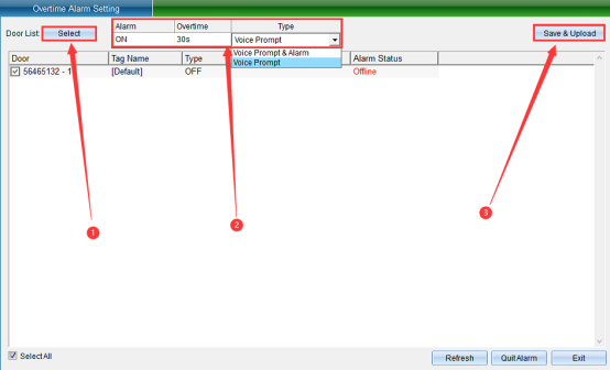
Select the equipment that needs to set the door opening timeout alarm function, then turn on the function, set the timeout time and prompt method (Timeout Prompt, No Alarm Output, Timeout Prompt, and Alarm Output). To cancel the alarm, click “Stop Alarm”. Then click “Save and Upload” to enter as shown in the following figure:
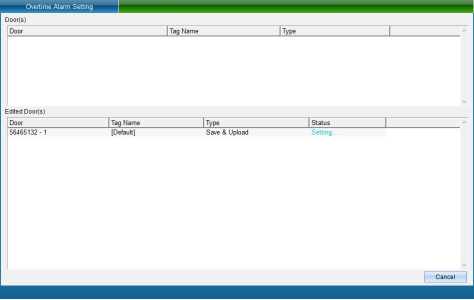
Click “Finish” to set the door opening timeout alarm successfully.
Door Magnetic Alarm Setting
Click “Access Control Information” - > “Alarm Function Setting” - > “Door Magnetic Alarm Setting”, as shown in the following figure:
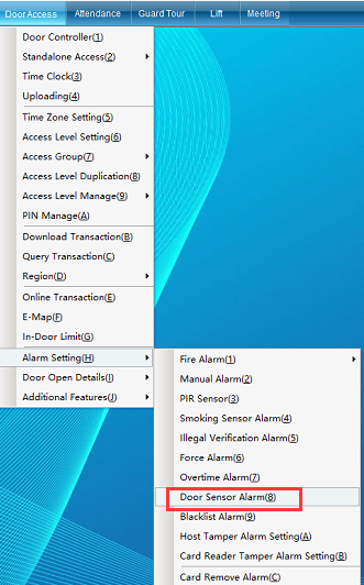
Click “Door Magnetic Alarm Setting” to enter the interface shown in the following figure:
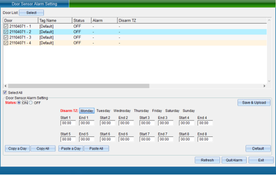
The door magnetic alarm is closed by default. After the door is not swiped legally, it is opened. You can set the corresponding time period not to enable the door magnetic alarm.
After selecting the equipment that needs to set the door magnetic alarm function, click to open this function, set the door magnetic related alarm parameters, and then click “Save and Upload” to enter the interface as shown in the following figure:
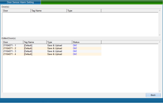
Click “Finish” to set the door magnetic alarm successfully.
Blacklist Alarm Settings
Click “Access Control Information” - > “Alarm Function Setting” - > “Blacklist Alarm” (this function is not available in the default interface. If you want to enable more required functions, you can click [enable function] in the [help] drop-down menu in the upper right corner of the main interface to enable more functions), as shown in the following figure:
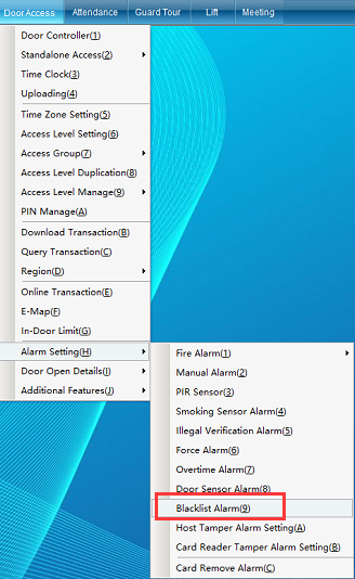
“Blacklist Alarm”: the software user will alarm immediately after being listed in the blacklist and swiping his card.
Click “Blacklist Alarm” to enter the interface shown in the following figure:
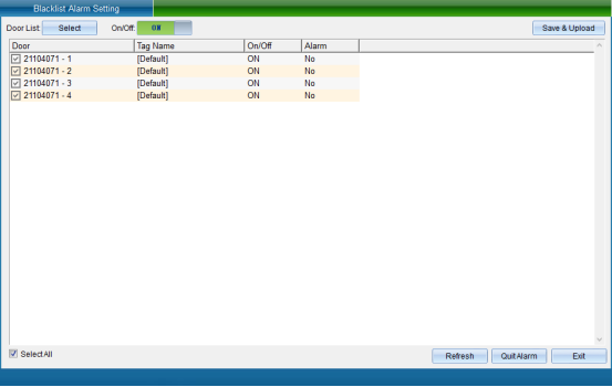
Select the device that needs to set the blacklist alarm function, turn on this function, and then click “Save and Upload”to enter the interface as shown in the following figure:
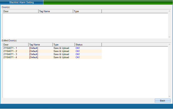
Click “Finish” to set the blacklist alarm.
Control panel anti disassembly alarm setting
Click “access control information” - > “alarm function setting” - > “control panel anti disassembly alarm setting” (this function is not available in the default interface. If you want to enable more required functions, you can click [open function] in the drop-down menu of [help] in the upper right corner of the main interface to open more functions), as shown in the following figure:
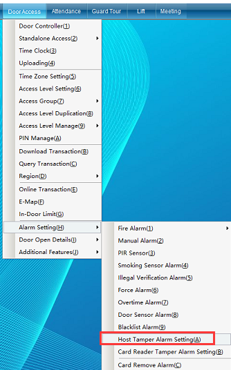
“Anti disassembly alarm setting of control board”: turn on this function. The alarm will be triggered if the mainboard is loose, dropped or removed.
Click “control panel anti disassembly alarm setting” to enter as shown in the following figure:
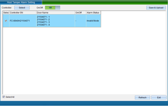
Select the door, set whether the selected door enables this function, and then click Save and Upload to enter the upload page, as shown in the following figure:
Click “Finish” to finish setting the tamper alarm of the control board.
Tamper alarm setting of card reader
Click “Access Control Information”- > “Alarm Function Setting” - > “Card Reader Tamper Alarm Setting” (this function is not available in the default interface. If you want to enable more required functions, you can click “Open Function” in the “Help” drop-down menu in the upper right corner of the main interface to open more functions), as shown in the following figure:
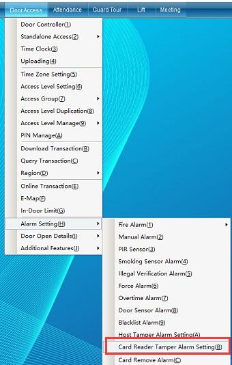
[Card Reader tamper alarm setting]: after this function is enabled, the system will automatically alarm when the card reader is illegally removed.
Click [card reader tamper alarm setting] to enter as shown in the following figure:

Select the door, set whether the selected door enables this function, and then click “Save and Upload” to enter the upload page, as shown in the following figure:
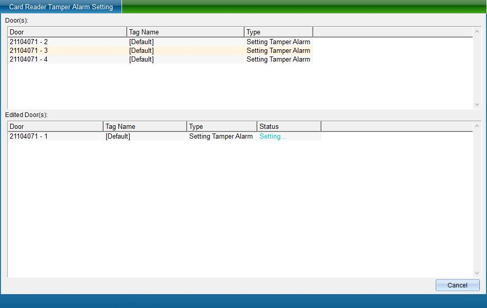
Click “Finish” to finish setting the anti disassembly alarm of the card reader.
Cancel alarm setting by swiping card
Click “Access Control Information” - > “Alarm Function Setting” - > “Card Swiping to Cancel Alarm Setting” (this function is not available in the default interface. If you want to enable more required functions, you can click “Enable Function” in the “Help” drop-down menu in the upper right corner of the main interface to enable more functions), as shown in the following figure:
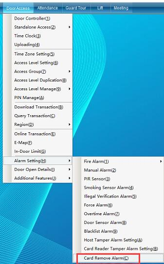
[card swiping to cancel alarm setting]: after this function is turned on, when the main board has alarm output, reading the registration card can cancel the alarm.
Click [card swiping to cancel alarm setting] to enter as shown in the following figure:
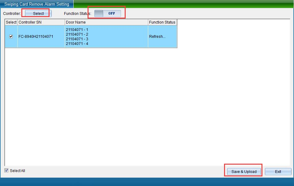
Select the door, set whether the selected door enables this function, and then click “Save and Upload” to enter the upload page, as shown in the following figure:
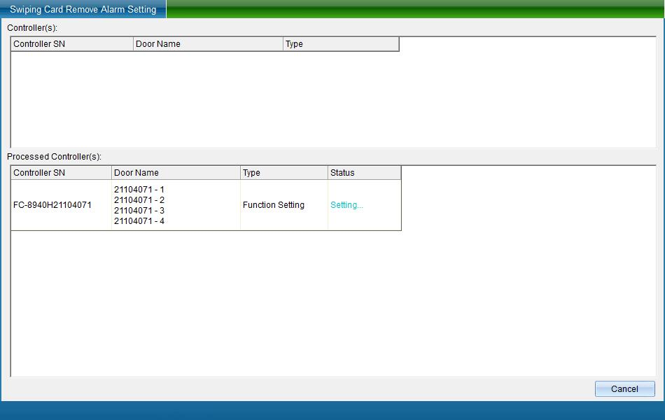
Click “Finish” to complete the setting of card swiping and alarm cancellation.
Door opening series function setting
Unlock hold setting
Click “Access Control Information” - > “Door Opening Function Setting” - > “Unlock Hold Setting” as shown in the following figure:
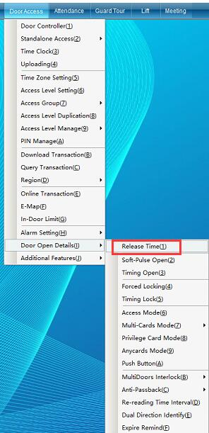
“lock hold setting”: it is the time from opening the door to closing the door. Select the corresponding door to set the delay time for opening the door. The minimum delay is adjustable by 0.5s and the maximum delay is adjustable by 65535s.
Click “Unlock Hold Setting” to enter the interface shown in the following figure:
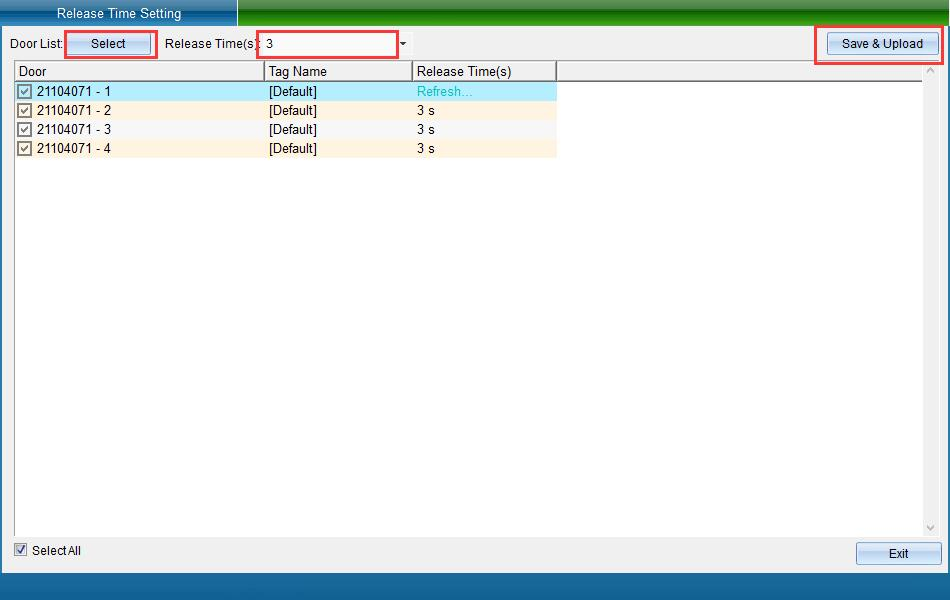
Select the equipment that needs to set the unlocking time. You can set the unlocking time of the door as required (the system defaults to 3 seconds), and then click “Save and upload” to enter the upload interface, as shown in the following figure:
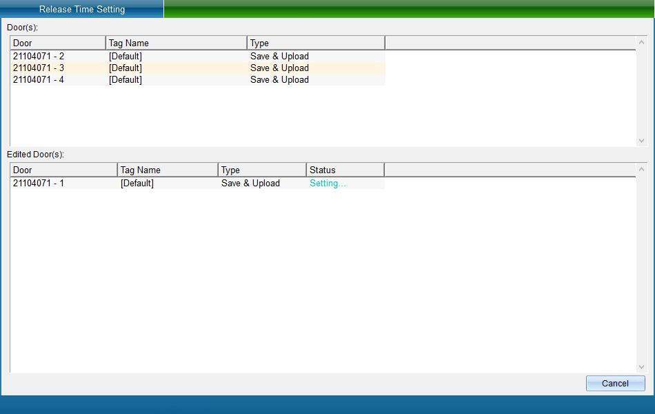
Click “Finish” to set the door unlocking time.
Remote Door Opening
Click “Access Control Information” - > “Door Opening Function Setting” - > “Forced Unlocking” (this function is not available in the default interface. If you want to enable more required functions, you can click “Open Function” in the “Help” drop-down menu in the upper right corner of the main interface to open more functions) as shown in the following figure:
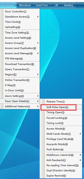
[Remote Door Opening]: you can set a door as normally open or remote door opening. If you cancel this function, click close to automatically restore the original state,
Please remember that the door magnetic signal must be connected to enable this function.
Click “Remote Door Opening” to open the interface as shown in the following figure:

After selecting the doors that need to be opened remotely, you can open, close, refresh the status of the selected doors remotely, or operate normally.
Click “Open Door” to see that the door controlled by the equipment is opened, and then click “Close Door” to close the door automatically.
Click “Normally Open” and the door will be in the normally open state. Without other operations, the door will not be closed.
Timed normally open setting
Click “Access Control Information” - > “Door Opening Function Setting” - > “Timed Normally Open Setting” (this function is not available in the default interface. If you want to enable more required functions, you can click [open function] in the drop-down menu of [help] in the upper right corner of the main interface to open more functions), as shown in the following figure:
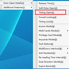
Click [timed normally open setting] to enter the interface shown in the following figure:
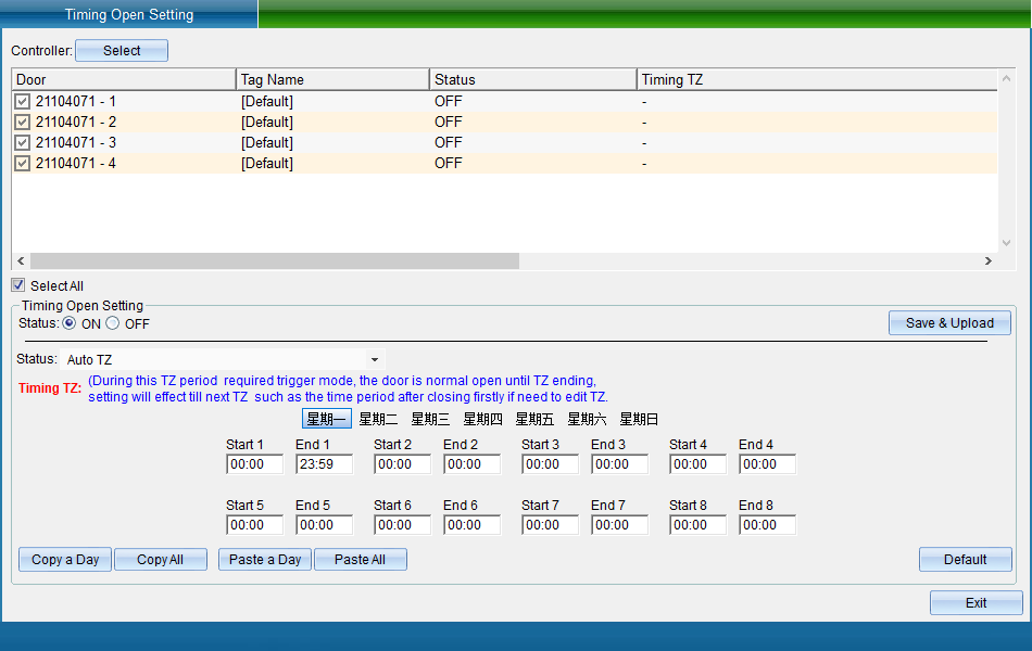
Select the equipment corresponding to the door that needs to be set to be normally open at a fixed time, and then enable the normally open at a fixed time. Set the time period from Monday to Sunday in the time period of the lock on and off at a fixed time. Set the normally open door according to the normally open trigger mode. After setting, click [save and upload] to pop up the interface as shown in the following figure:
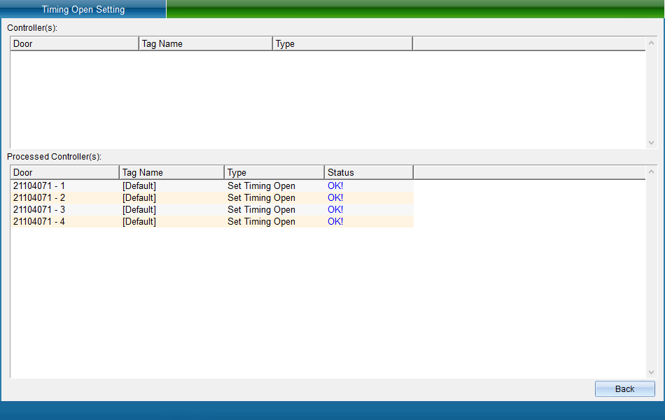
Click “Finish” to set the scheduled door opening period.
Timing switch lock period: during this period, it needs to be normally open according to the trigger mode. After opening the door, the lock can be closed until the end of the period.
Normally open trigger modes include: the registration card is normally open during the period, the normally open card is normally open during the period, and the switch lock is set according to the period.
Note: the timed normally open setting conflicts with the anti sneak back function and cannot be used at the same time.
Remote lock door
Click “Access Control Information” - > “Door Opening Function Setting” - > “Forced Locking” (this function is not available in the default interface. If you want to enable more required functions, you can click [open function] in the [help] drop-down menu in the upper right corner of the main interface to open more functions) as shown in the following figure:
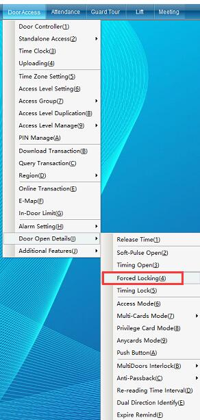
“Remote Locking” the purpose of forced locking is to lock a control port (door) of the door lock controller for use. After locking, the device will turn off the door switch, card reading, door opening, wireless remote control and other functions and cannot be used. After unlocking, the port (a door) will be automatically restored to use.
Click “Remote Lock” to enter the interface shown in the following figure:
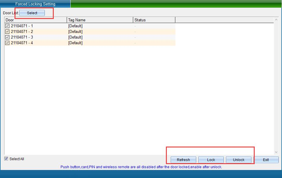
Select the door to be locked, and then click “Lock” to lock the door. The locked door can be opened by disabling the door opening switch, swiping card to open the door, wireless remote control, etc. its function can be used to open the door only after unlocking. To unlock, click “Unlock” to unlock the locked door.
Timing lock door setting
Click “Access Control Information” - > “Door Opening Function Setting” - > “Timed Locking Door Setting” (this function is not available in the default interface. If you want to enable more required functions, you can click “Open Function” in the drop-down menu of “Help” in the upper right corner of the main interface to open more functions), as shown in the following figure:
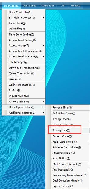
Click “Timing Lock Door Setting”to enter the interface shown in the following figure:
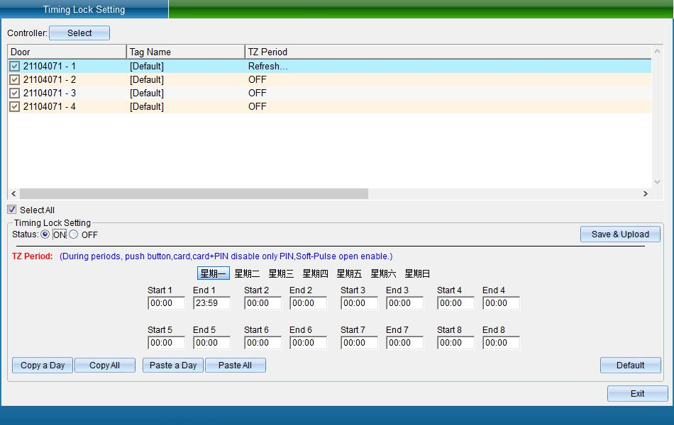
Select the door to be locked, open the timing lock, set the lock time from Monday to Sunday, and then click Save and Upload to enter the interface as shown in the following figure:
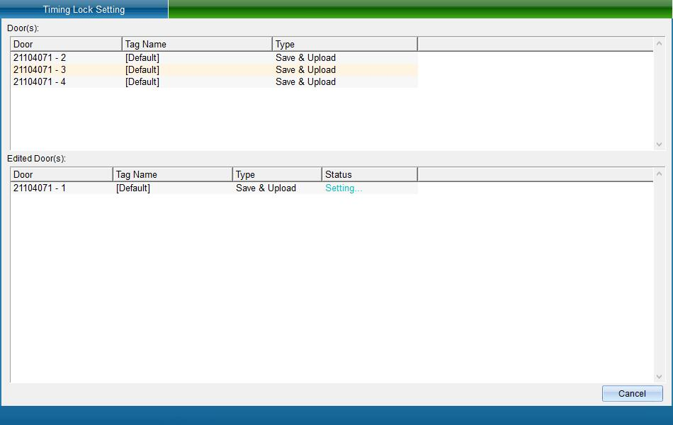
Click “Finish” to set the locking door successfully.
When enabling the setting of timed door lock, click the time to enable the setting of timed door lock and the effective period, and then click “Save and Upload” and exit. After enabling “Timing Lock Door Setting”, during these periods, door opening switch, card reading, card plus password, etc. cannot be opened, and only password and remote unlocking are valid
Access Certification Method
There are four kinds of entry and exit authentication methods: card reading, password, card + password, manual input card + password.
+: swipe the card, enter the password, and press the # key to confirm.
+: press the * key, enter the card number, press the # key, enter the password, and press the # key.
Click “access control information” - > “door opening function setting” - > “access authentication method” (this function is not available in the default interface. If you want to enable more required functions, you can click [open function] in the drop-down menu of [help] in the upper right corner of the main interface to open more functions), as shown in the following figure:
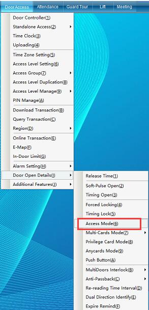
“Access Authentication Method” you can set different card swiping verification methods every day according to the week and set different times according to the time period to realize a certain way of opening the door.
Click “Entry / Exit Authentication Method” to enter the interface shown in the following figure:
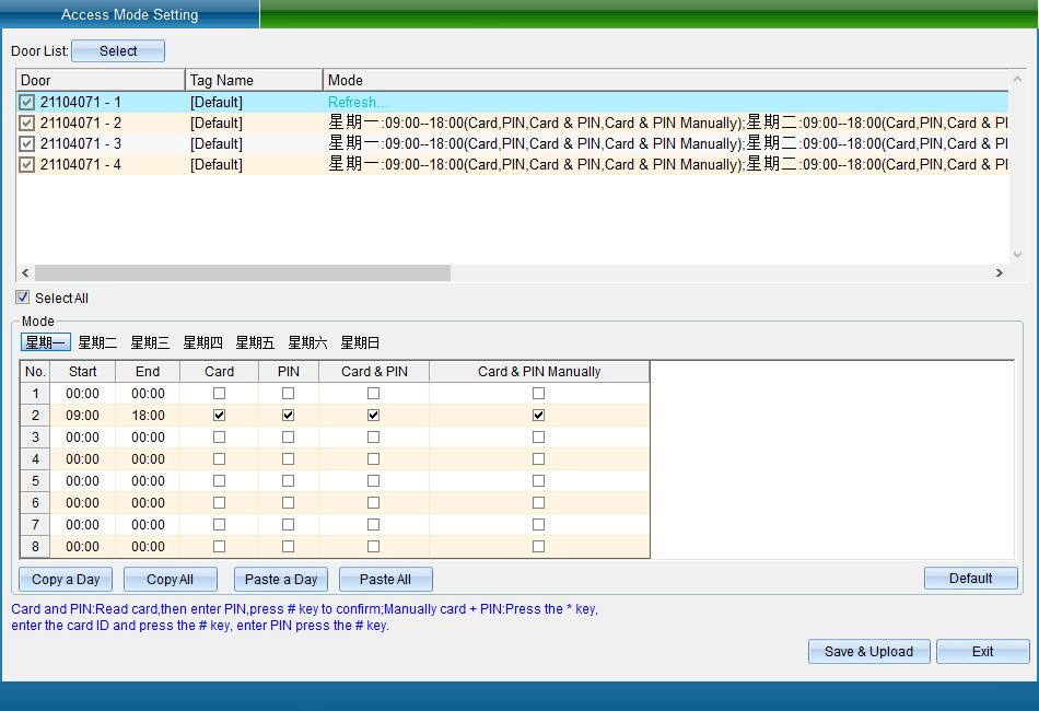
Select the equipment that needs to set the access authentication method, set the authentication time period and authentication method from Monday to Sunday, and then click [save and upload] to enter the upload interface, as shown in the following figure:
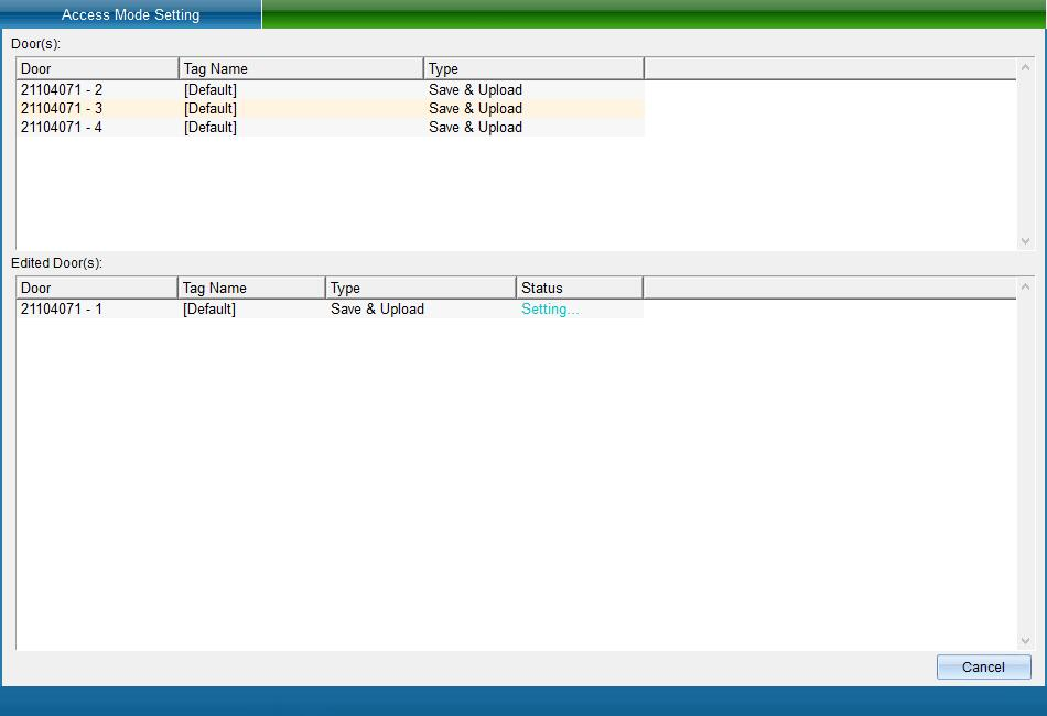
Click Finish to set the access authentication method successfully.
For example, the above settings: on Monday, you can set 08:00-12:00 to open the door effectively, and the password opening, card plus password opening and manual card plus password opening are invalid; 13:00-15:00 use password to open the door; 16:00-18:00 use card and password to open the door; 19:00-21:00 enter the card password manually; From 22:30 to 22:00, you can open the door by reading the card or password; 22:30-23:59 card reading, password, card + password, manual input card + password buckle can open the door. Set different door opening methods and select door opening according to user requirements.
Prompt for card expiration in advance
Prompt in advance of Card Expiration: refers to the voice prompt every time the card is swiped within 30 days before the card expires.
Click “access control information” - > “door opening function setting” - > “card expiration prompt” (this function is not available in the default interface. If you want to enable more required functions, you can click [open function] in the drop-down menu of [help] in the upper right corner of the main interface to open more functions), as shown in the following figure:
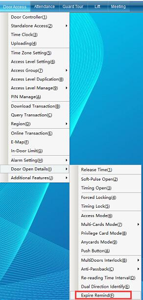
Click “Card Expiration Reminder” to enter the following figure:
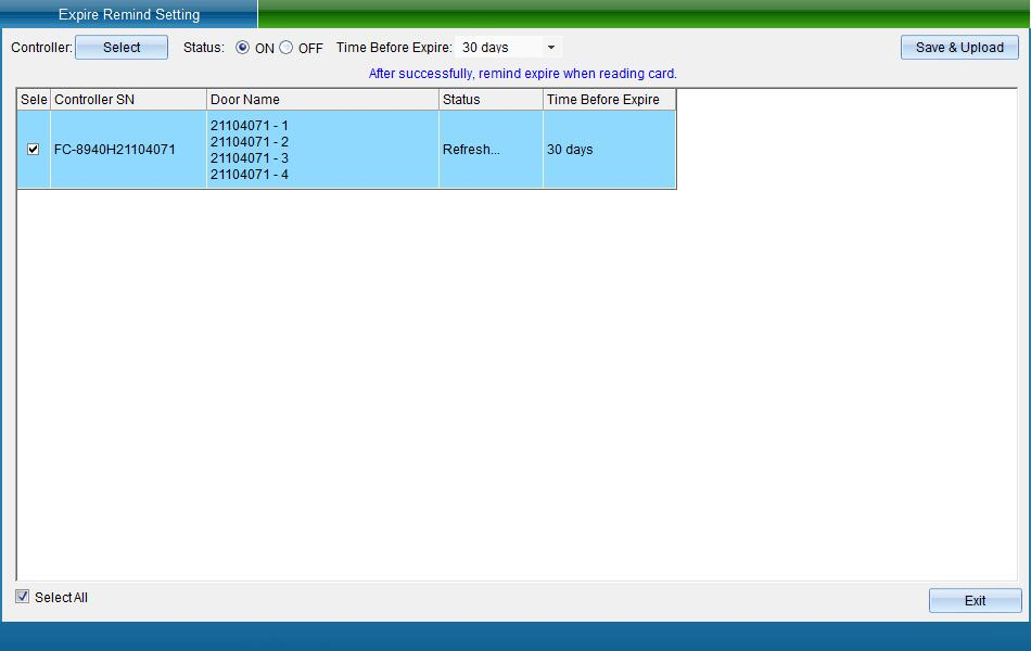
Select the access controller that needs to set the card expiration reminder, whether to enable this function, set the reminder time before expiration, and then click Save and upload to enter the upload interface, as shown in the following figure:
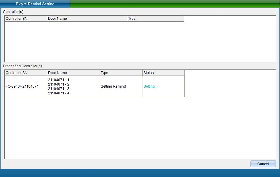
Click Finish to set the card expiration reminder function successfully.
Other function settings
Other function settings can be divided into holiday settings, timed card reading settings, voice broadcast settings, card reading voice settings, etc.
Holiday setting
Click [Access Control Information] - > [Other Function Settings] - > [Holiday Settings] (this function is not available in the default interface. If you want to enable more required functions, you can click [open function] in the [Help] drop-down menu in the upper right corner of the main interface to open more functions), as shown in the following figure:
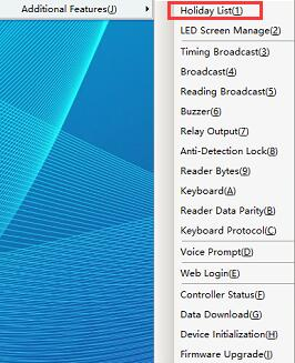
Click “Holiday Setting” to enter the interface shown in the following figure:
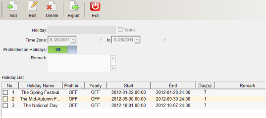
Click “Add”, enter the holiday name, start and end time periods and holiday descriptions, and then click [save] (as shown in figure 1-13-3). It can be accurate to half a day. It can set whether to cycle every year according to the specific situation, and define the door opening permission on holidays.
After clicking “Save”, you can see the new holidays in the holiday list, and you can modify and delete the holidays. Select the holidays that need to be modified and deleted, click “Modify” or “Delete”, and then click “Save” to complete the modification and deletion.
Unlock Output Mode
Click “access control information” - > “other function settings” - > “unlock output mode” (this function is not available in the default interface. If you want to enable more required functions, you can click [open function] in the [help] drop-down menu in the upper right corner of the main interface to open more functions), as shown in the following figure:
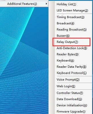
Click “Unlock Output Mode” to enter the interface as shown in the following figure:
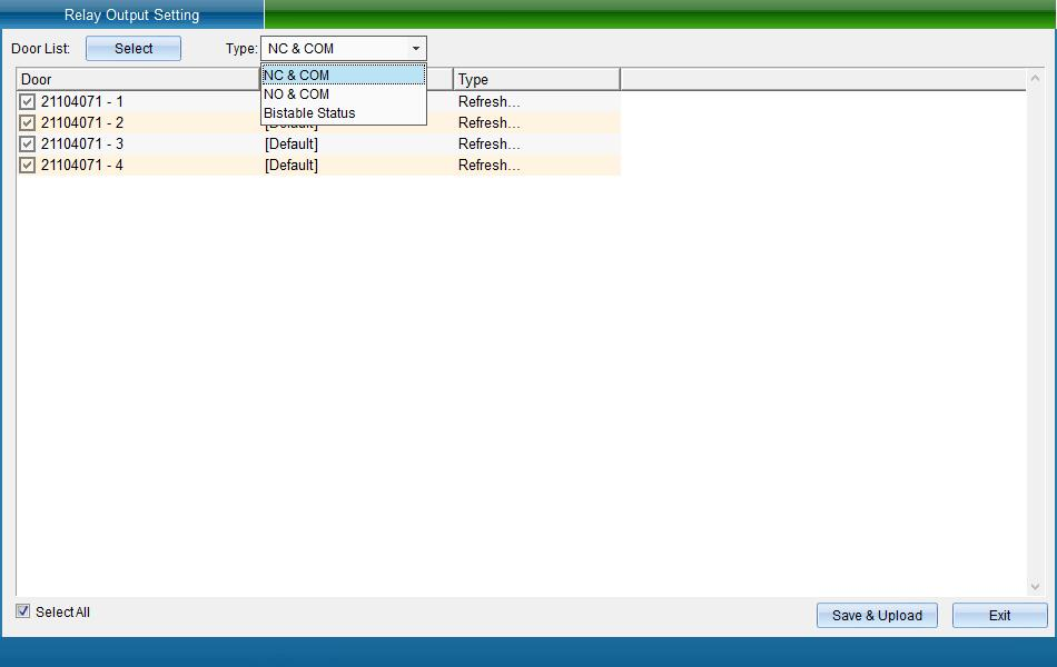
The user can select the relay output mode. Card reading switching (bistable) refers to opening the door by swiping the card for the first time and closing the door by swiping the card for the second time.
Anti detection locking setting
Anti detection lock: after swiping more than 4 illegal cards in a row, the anti detection lock will be opened, and it will not be automatically released until one minute.
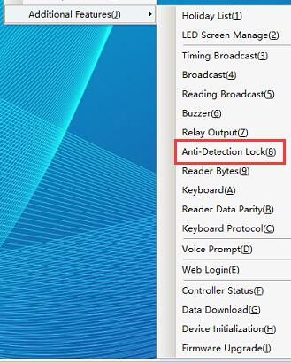
Click [Access Control Information] - > [Other Function Settings] - > [Anti Detection Locking Settings] (this function is not available in the default interface. If you want to enable more required functions, you can click [Open Function] in the [Help] drop-down menu in the upper right corner of the main interface to open more functions), as shown in the following figure:
Click [Anti Detection Locking Setting] to enter the interface shown in the following figure:
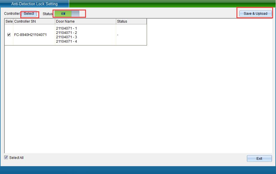
Select the device and turn on the function, and then click [Save and Upload]. Enter the interface shown in the following figure:
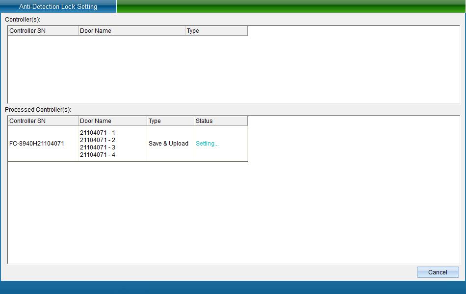
Click [Finish] to set the anti detection lock successfully.
Reader byte setting
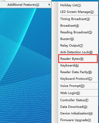
Click [Access Control Information] - [Other Function Settings] - [Reader Byte Settings] as shown in the following figure:
Click [Reader Byte Setting] to enter the interface shown in the following figure:
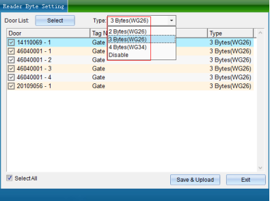
It can be converted into required bytes according to the card number; We use weigen26 3 bytes by default. Different bytes read different card numbers. Please note: the setting of this function will cause abnormal use. Please enable it carefully. Unless you must use this function, we don't recommend you to use it.
Reader keyboard settings
Click [Access Control Information] - > [Other Function Settings] - > [Card Reader Keyboard Settings] as shown in the following figure:
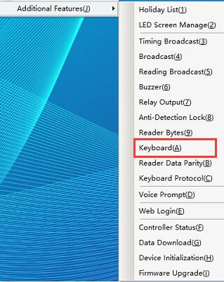
Click [Card Reader Keyboard Setting] to enter the interface shown in the following figure:
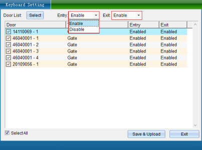
If the keyboard reader is installed, you can set whether to use the keyboard password for management. The figure shows the relevant operation commands of keyboard management:
Reader data verification settings
Click [Access Control Information] - > [Other Function Settings] - > [Card Reader Data Verification Settings] as shown in the following figure:
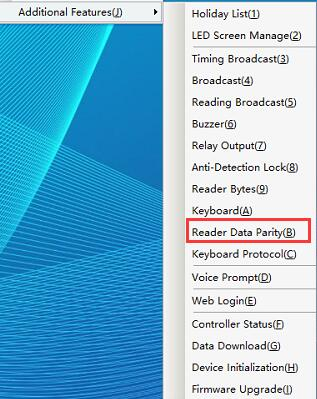
Click [Card Reader Data Verification Settings] to enter as shown in the following figure:
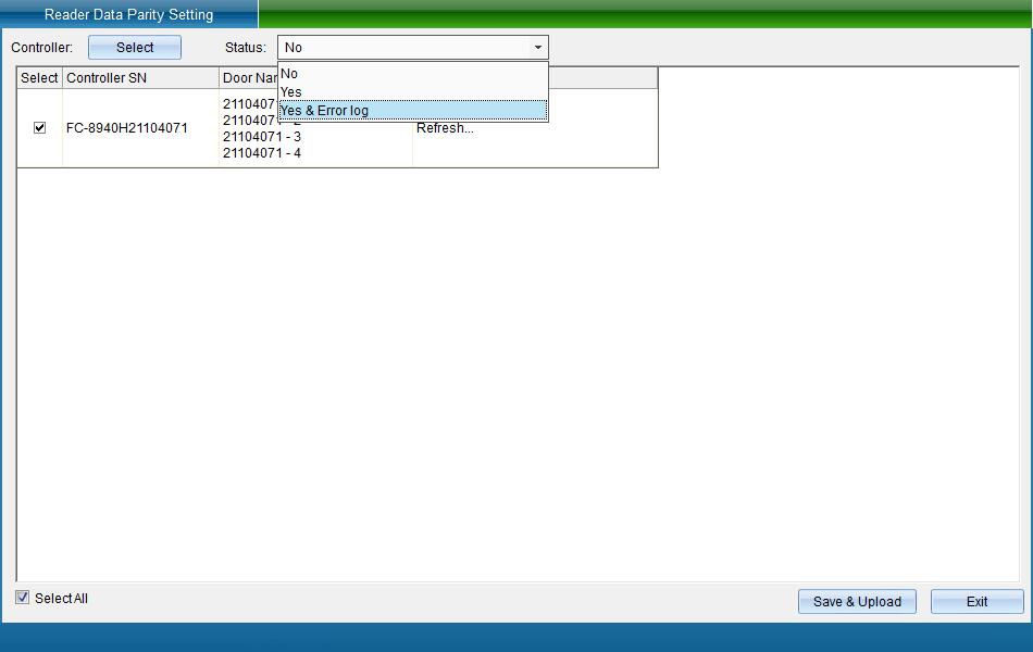
Automatically identify the connection error of the card reader and the wiegand signal protocol of the card reader, which is used to verify whether the data transmitted by the card reader is standard, and support the automatic detection of whether the wiegand signal lines 0 and 1 are connected well, whether they are connected inversely, etc. (if the signal line is found to be connected incorrectly, it will be notified and prompted). The default is to enable verification. If the card reader you are using is non-standard output, please turn off this function, otherwise you will not be able to use your non-standard card reader because the verification fails.
Password keyboard management function
Click [Access Control Information] - > [Other Function Settings] - > [Password Keyboard Management Function] as shown in the following figure:
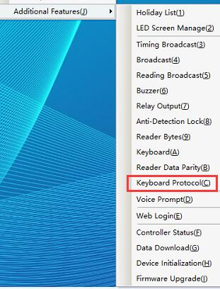
Click [Password Keyboard Management Function] to enter the interface shown in the following figure:
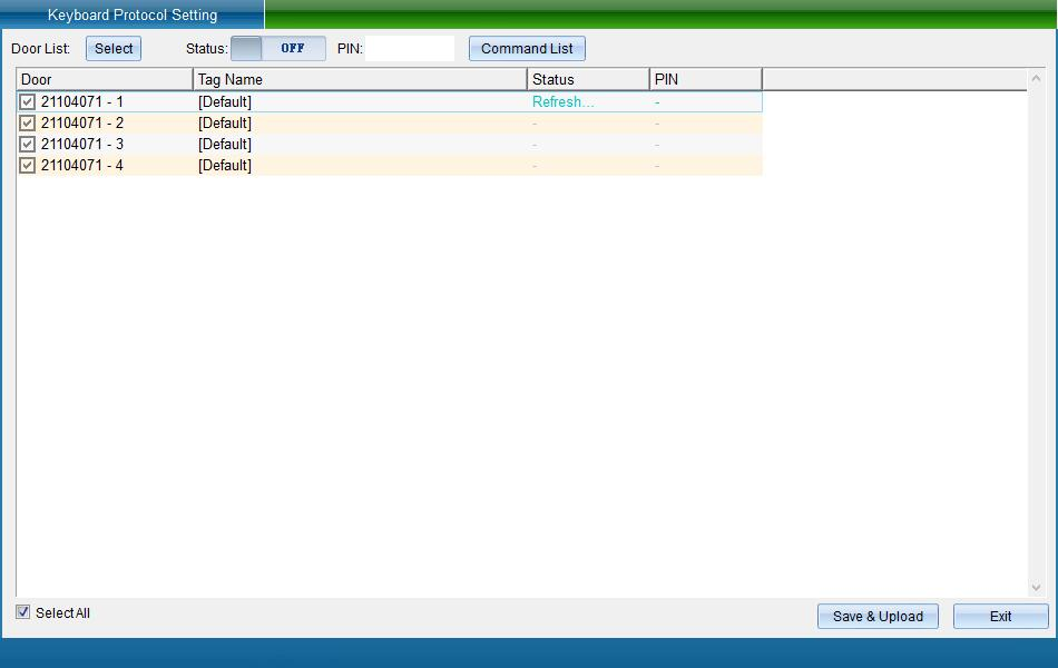
Click [Keyboard Command Table] to view the command operation, as shown in the following figure:
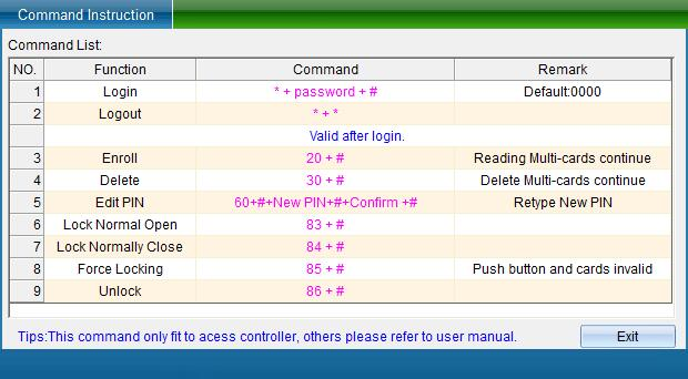
After viewing, click [Exit] to return to the password keyboard management function interface.
To open the "password keyboard management function", enter the keyboard password and click [Save and Upload].
Get data from device
When a user accidentally deletes all the data of the software, he can extract the personnel card number, door opening password and door opening period from the equipment, and save the obtained information to the database again.
Click [Access Control Information] - > [Other Function Settings] - > [Get Data from Device] as shown in the following figure:
Click [Get Data from Device] to enter the interface shown in the following figure:
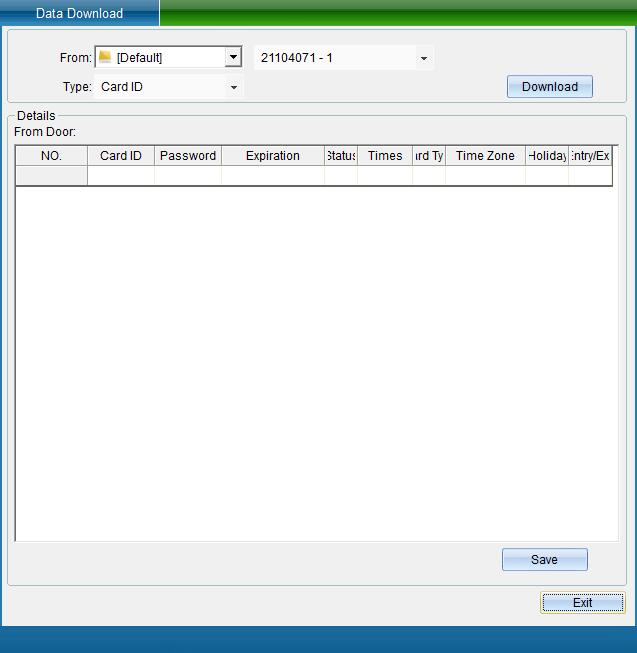
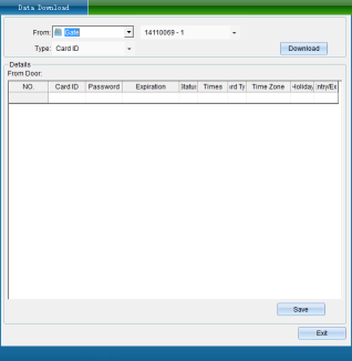
If the selected device is a fingerprint machine / face machine, there will be an 'collect fingerprint, face' button next to the acquired data, as shown in the following figure:
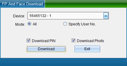
Click 'Collect Fingerprints' to retrieve all fingerprints from the fingerprint machine or the fingerprints of the specified user, as shown in the following figure:
Get card number
Select the door and equipment, select to obtain the card number data, and then click [start to obtain data], the data obtained from the equipment will be displayed (as shown in figure 1-13-23), and a prompt window "obtaining the card number is completed, the number of card numbers obtained is XX" will pop up, indicating how many card numbers are obtained from the equipment, click [OK].
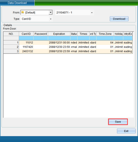
Click [Save to Database] to save the data obtained from the door to the database. After saving, a prompt window "saving data completed" will pop up, indicating that saving to the database is successful.
Get the door opening password
When the data type selected is door opening password. Click [start to get data], the obtained door opening password will be displayed, and a prompt window will pop up, as shown in the following figure:
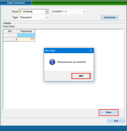
Click OK to save the obtained data to the database, and click Save to database to pop up a prompt window, as shown in the following figure:
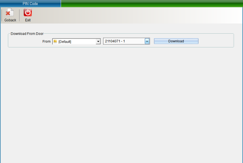
Click OK to save the data.
Get the opening period
If the selected data is the door opening period, click [Start Acquiring Data], and the acquired data will be displayed, as shown in the following figure:
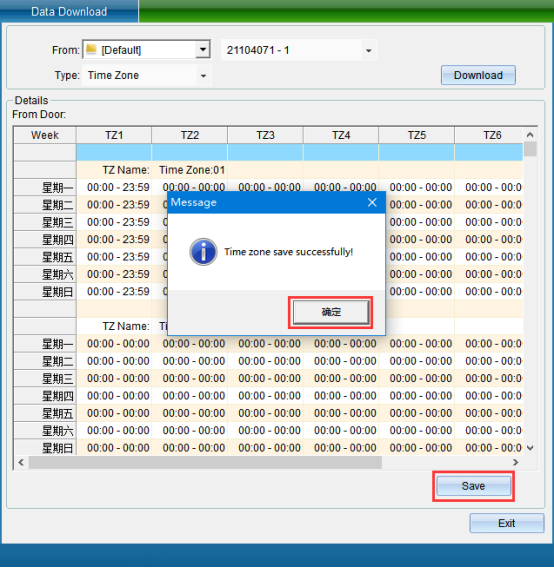
After data acquisition, a prompt window pops up, and click OK in the prompt window to complete data acquisition.
You can also save the obtained data to the database, and click Save to database to pop up a prompt window, as shown in the following figure:
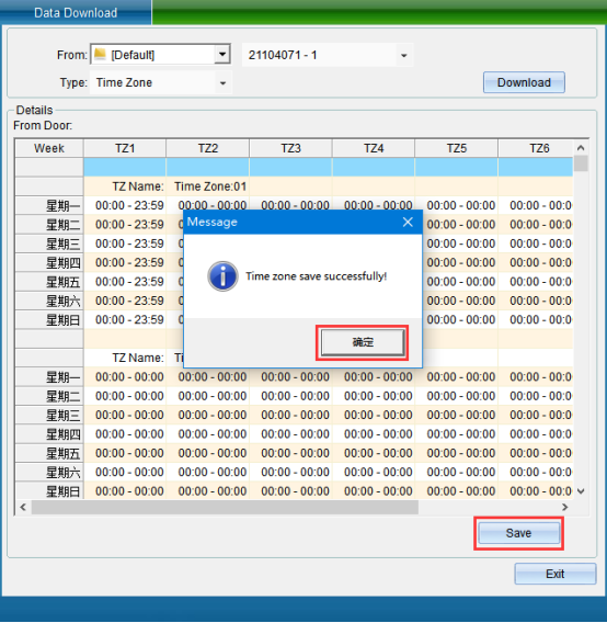
Click OK in the prompt window to save the data to the database.
Initialize Device Data
Click [Access Control Information] - > [Other Function Settings] - > [Initialize Access Control Equipment] as shown in the following figure:

Click [Initialize Access Control Equipment] to enter as shown in the following figure:
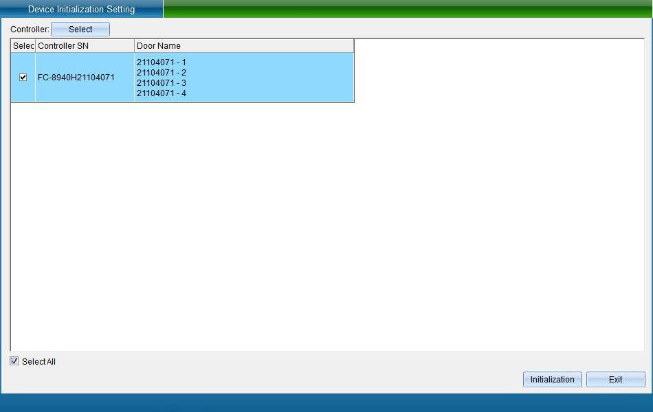
Click [Initialize Device] to restore the controller data to the factory default value.
Controller function status
To check the functions of the controller, click [Access Control Information] - [Other Function Settings] - [Controller Function Status] in the software menu, as shown in the following figure:
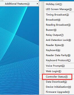
Click [Controller Function Status] to enter as shown in the following figure:
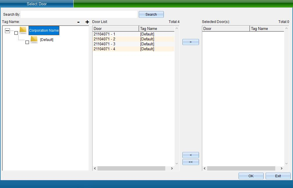
Select a device to view, and the pop-up is shown in the following figure:

To continue to view other devices, click [select the controller to be operated] to select.
Software voice prompt settings
If the equipment is abnormal, voice prompts can be set to find problems and repair them in time.
In the main interface of the system, click [access control information] - [other function settings] - [software voice prompt settings], as shown in the following figure:
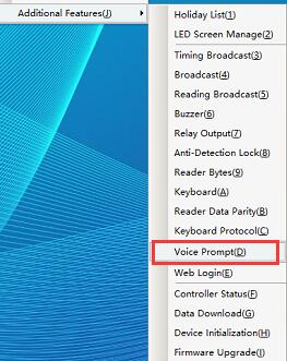
Click [Software Voice Prompt Setting] to pop up the interface as shown in the following figure:
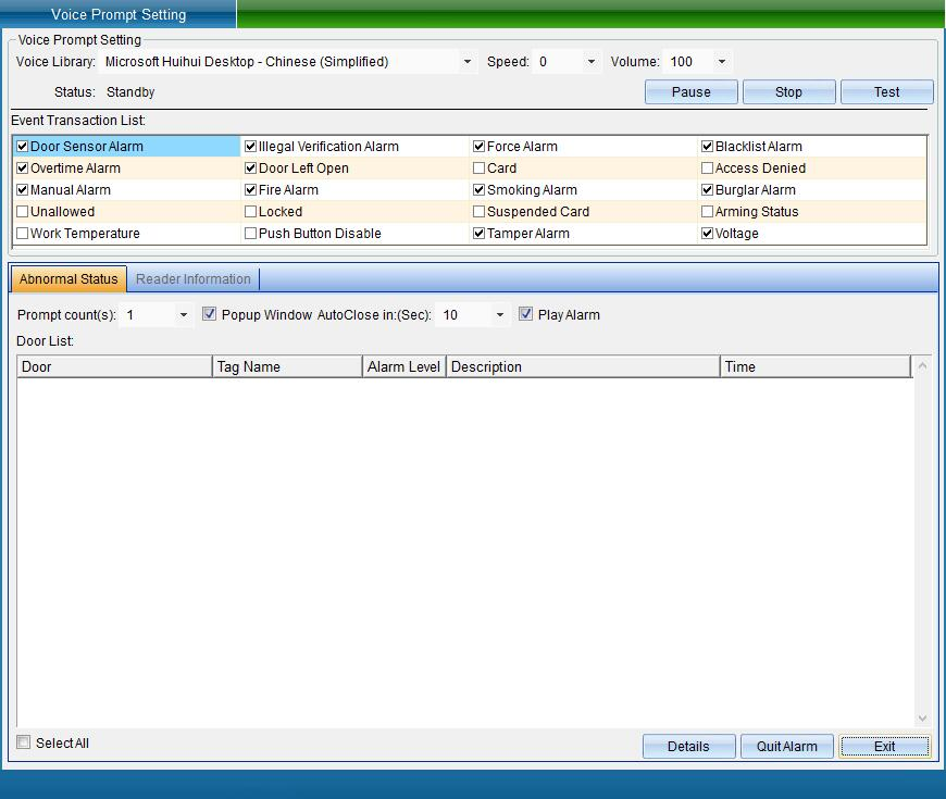
In this interface, the voice items that can be set include access control alarm, unregistered card alarm, coercion alarm, etc. when some items occur, there will be voice prompts.
Firmware Online Upgrade
Click [Access Control Information] - > [Other Function Settings] - > [Firmware Online Upgrade] (this function is not available in the default interface. If you want to enable more required functions, you can click [Enable Function] from the [Help] drop-down menu in the upper right corner of the main interface to enable more functions), as shown in the following figure:
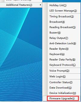
Click [Firmware Online Upgrade] to enter the interface shown in the following figure:
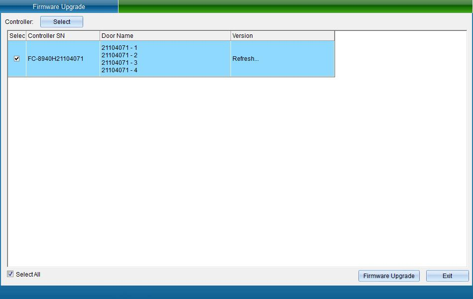
Select the device to be upgraded and click [Firmware Upgrade]. Enter the interface shown in the following figure:
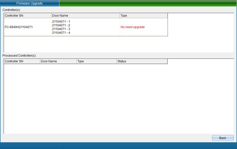
After upgrading, click "Finish".